All of these add up to 4.9951171875, meaning binary 1111111111, or one LSB less than 5. The MSB will remain set until the input is one half the reference voltage, 2.5 V. As the voltage is decreased to 4.9 V, only some of the least significant bits are cleared. Since the reference voltage is 5 V, when the input voltage is also 5 V, all bits are set. Approximation value on the y axis.Įxample: The ten steps to converting an analog input to 10 bit digital, using successive approximation, are shown here for all voltages from 5 V to 0 V in 0.1 V iterations. Operation of successive Approximation ADC as input voltage falls from 5 to 0 V.


Analog to digital converter diagram code#
The resulting code is the digital approximation of the sampled input voltage and is finally output by the SAR at the end of the conversion (EOC). Then the next bit is set to 1 and the same test is done, continuing this binary search until every bit in the SAR has been tested. If this analog voltage exceeds V in, then the comparator causes the SAR to reset this bit otherwise, the bit is left as 1. This code is fed into the DAC, which then supplies the analog equivalent of this digital code ( V ref/2) into the comparator circuit for comparison with the sampled input voltage. The successive approximation register is initialized so that the most significant bit (MSB) is equal to a digital 1. This causes the comparator output to change state and triggers the control logic stage to stop the counting.Animation of a 4-bit successive-approximation ADC After this, the output of the integrator which is also the input of the capacitor begins dropping at a constant rate.ĭuring this period, the counter keeps advancing, while the output of the integrator continues to drop at a constant rate, until it goes below the reference voltage of the comparator. When the fixed time interval finishes, the count is set to 0, which prompts the electronic switch to connect the integrator to a fixed reference input voltage level. Referring to the (b) section of the diagram above, shows that the voltage from the integrator at the end of the fixed time interval is higher than the input voltage that's larger in magnitude. For this interval the input analog voltage applied to the integrator causes the comparator input voltage to rise to some positive level.
Analog to digital converter diagram full#
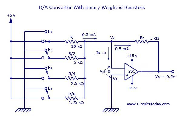
The full measuring range of the counter decides the fixed time interval. The method may be understood with the following description: The output voltage is proportionate to the digital input value as expressed by the equation: The figure below demonstrates a ladder network using 4 input voltages, that represent 4 bits of digital data and a dc voltage output. One well-known method utilizes a network of resistors, known as ladder network.Ī ladder network is designed to accept inputs involving binary values typically at 0 V or Vref and delivers an output voltage equivalent to the magnitude of the binary input. How Digital-to-Analog Converters Workĭigital-to-analog conversion process can be carried out through many different techniques. In a analog to digital converters (ADC), the input analog signal is represented as a digital magnitude, while a digital-analog converter (DAC) converts the digital magnitude back to an analog signal. In digital circuits the voltage signal is in two forms, either as a logic high or logic low logic levels, which represent binary values of 1 or 0.

In electronics we may find voltages and currents varying continuously with different ranges and magnitudes.

In this article we comprehensively discuss how digital to analog, and analog to digital converter circuits work, using diagrams and formulas.


 0 kommentar(er)
